
Your telescope’s real focal length is rarely the number on the box – and on mirror-spacing designs (RC, SCT, Cassegrain) it drifts with collimation and focus position. This calculator measures the truth with a plate solve and, for adjustable designs, tells you which mirror to move, which direction, and how far.
Step 1: Manufacturer Optics #
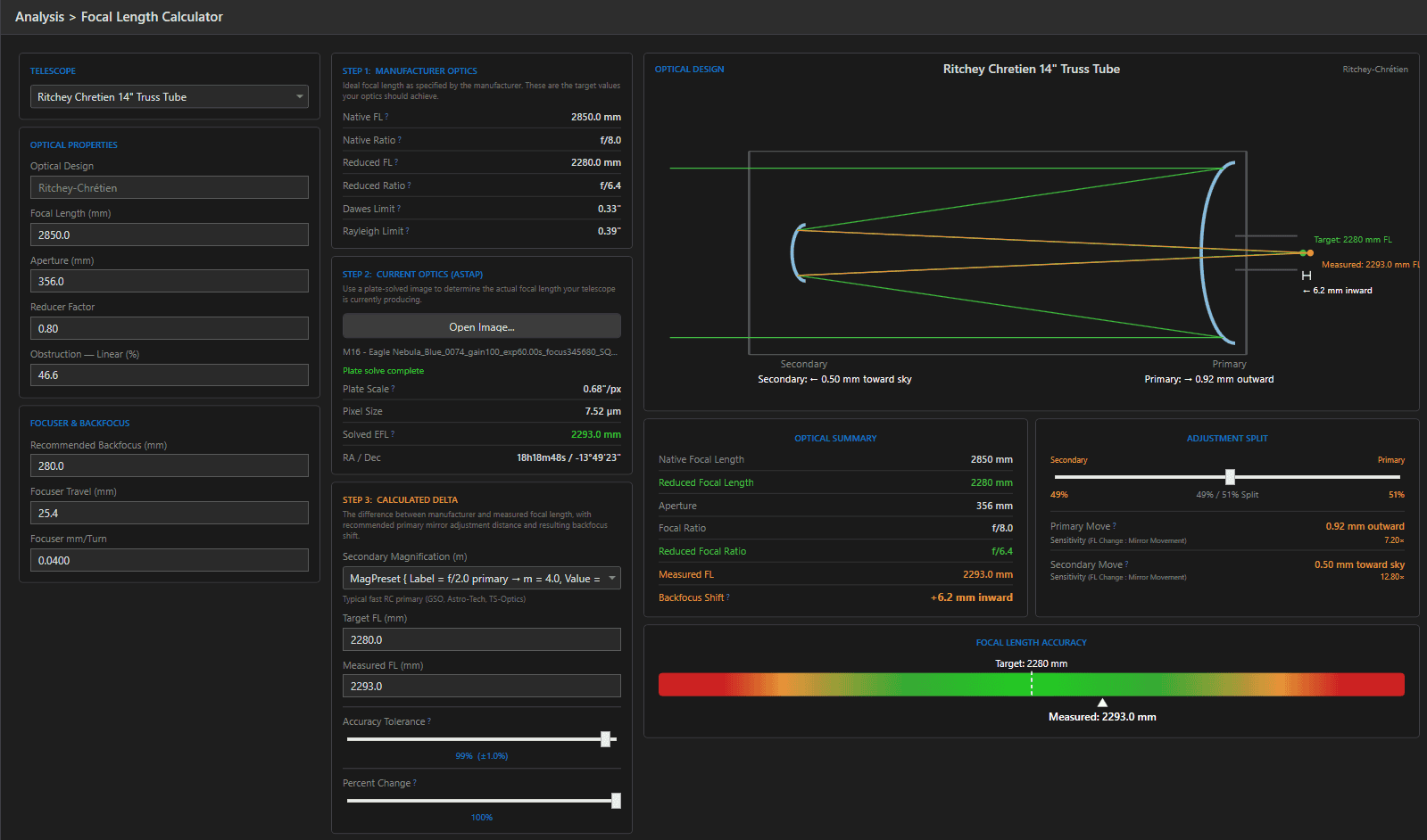
Select the telescope and the spec-sheet numbers populate: native and reduced focal length, focal ratios, Dawes and Rayleigh limits. These are the targets the measurement will be compared against. Backfocus and focuser travel fields round out the mechanical picture.
Step 2: Measure With a Plate Solve #
Open any recent sub (FITS, XISF, TIFF – XISF is converted automatically) and the calculator runs ASTAP on it. The solved plate scale plus the pixel size from the image header yield the measured effective focal length:
EFL = 206.265 × pixel size (µm) / plate scale (arcsec/px)
This is ground truth – the focal length your optical train actually delivered on that frame, including reducer, spacing, and temperature effects.
Step 3: The Delta & Mirror Adjustment #
For adjustable designs the calculator turns the target-vs-measured difference into mechanical guidance. The key concept is secondary magnification (m) – how much the secondary mirror amplifies the primary’s focal length. Presets cover the common designs (e.g. an f/8 GSO-style RC uses an f/2 primary, m = 4; an EdgeHD runs m ≈ 5.26), or enter your own.
Why m matters: mirror-spacing changes are amplified by m² at the secondary – on an m = 4 RC, moving the secondary 0.1mm changes focal length roughly 16× more than the same move of the primary. The calculator computes both options with their sensitivities, and an adjustment split slider lets you distribute the correction between mirrors. Direction is spelled out in plain words (“0.05 mm toward sky”), along with the focuser backfocus shift that compensates.
The Accuracy Bar & Tolerance #
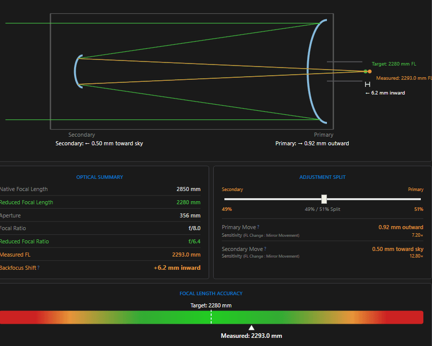
A gradient bar visualizes where the measured focal length sits: green zone = within your chosen tolerance (default 98%, i.e. ±2%), amber and red beyond. The Percent Change slider scales the recommended correction if you deliberately want a partial move – useful when chasing a target in small, safe steps.
The Optical Diagram #
The right-hand panel draws your telescope’s optical layout – primary, secondary, and focal plane – annotated with the ideal and measured light paths, plus a live summary of every figure: native and reduced focal length and ratio, measured EFL, backfocus shift, and the per-mirror moves with their sensitivities. A screenshot of this panel is the perfect note to keep with your maintenance log.